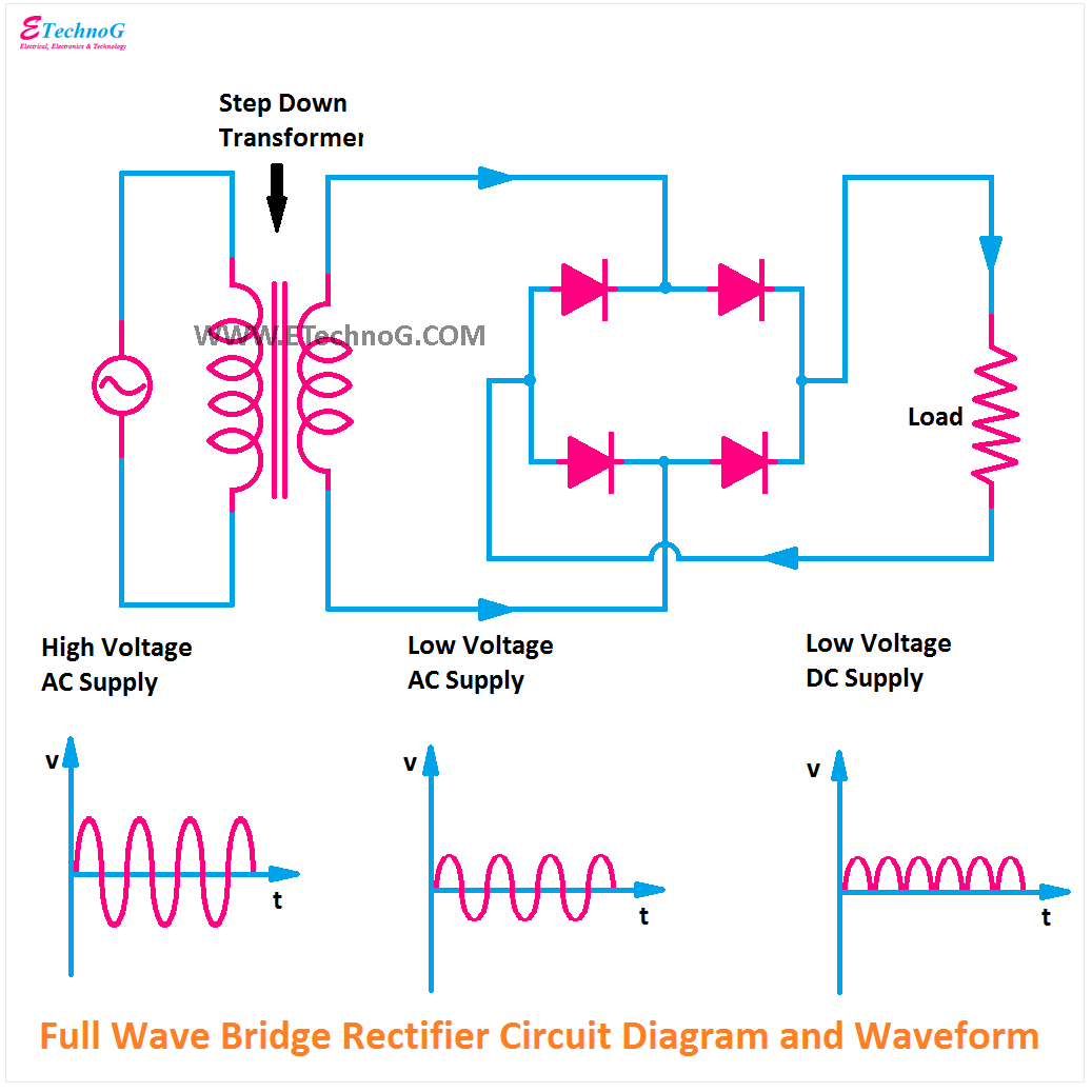
Rectifier bridge wave circuit diagram diode voltage operation peak fig its shown below inverse value when negative Full wave bridge rectifier Rectifier bridge output input wave voltage ac using without dc 230v transformer waveforms diode source block ltspice any arbitrary simulating
Rectifier Circuit Diagram | Half Wave, Full Wave, Bridge - ETechnoG
Custom designed axial flux motor
Rectifier wave waveform output electronics tutorials gif
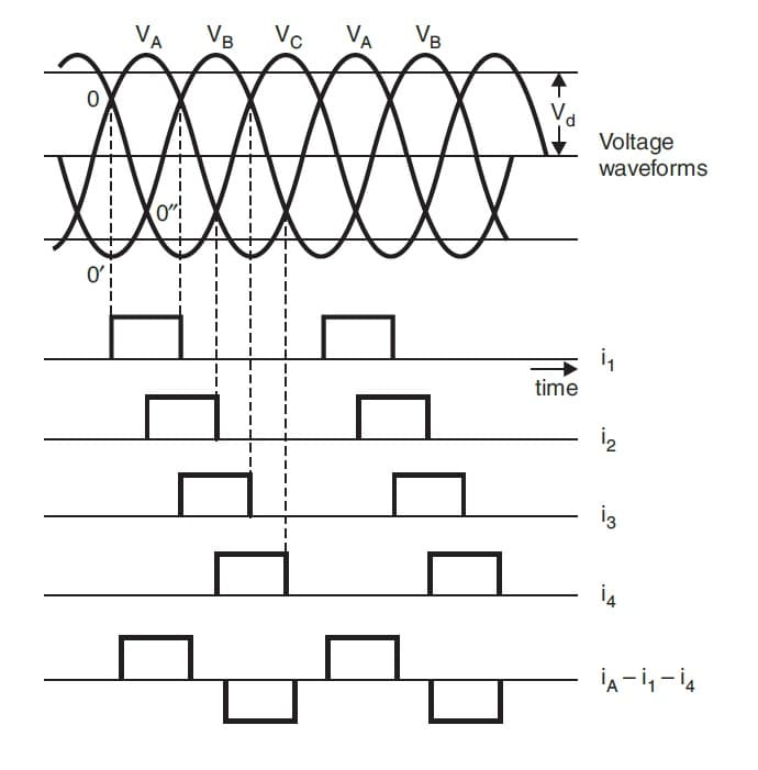
Rectifier wave bridge capacitor smoothing output waveform will standards electrical increase above dcThree phase full wave rectifier working, diagram and output waveform Rectifier output dc wave bridge waveform circuit diagram voltage input principle working positive convertsWave rectifier bridge oscilloscope circuit understanding help diodes analysis.
The full-wave bridge rectifierElectrical standards: full wave rectifier; full wave bridge rectifier Rectifier waveform capacitorRectifier waveform voltage.

Full wave bridge rectifier – circuit diagram and working principle
Full wave bridge rectifier – circuit diagram and working principle5730 smd help. Wave bridge rectifierRectifier waveform capacitor signal resistor circuitglobe.
Rectifier circuit diagramFull-wave rectifier output waveform Rectifier wave circuit bridge voltage output working transformer tapped centre across load advantages consistsFull wave bridge rectifier || electronics 1 || bangla.

Full wave rectifier
Rectifier bridge circuit diagram phase half wave rectification motor voltage figure dc current waveforms engineeringCircuit analysis Rectifier voltage pulsating fullwave converts.
.


