Understanding FPGA Programming and Design Flow - HardwareBee

Full Adder Circuit Diagram In Verilog

Verilog full adder example Verilog adder example fulladder below gates exercises basis form will

Adder verilog behavioral logic truth cout technobyte 10+ adder circuit diagram Adder circuit diagram basic gates using truth table

10+ Adder Circuit Diagram | Robhosking Diagram

Adder verilog

Verilog adder code structural using behavioral project implemented both

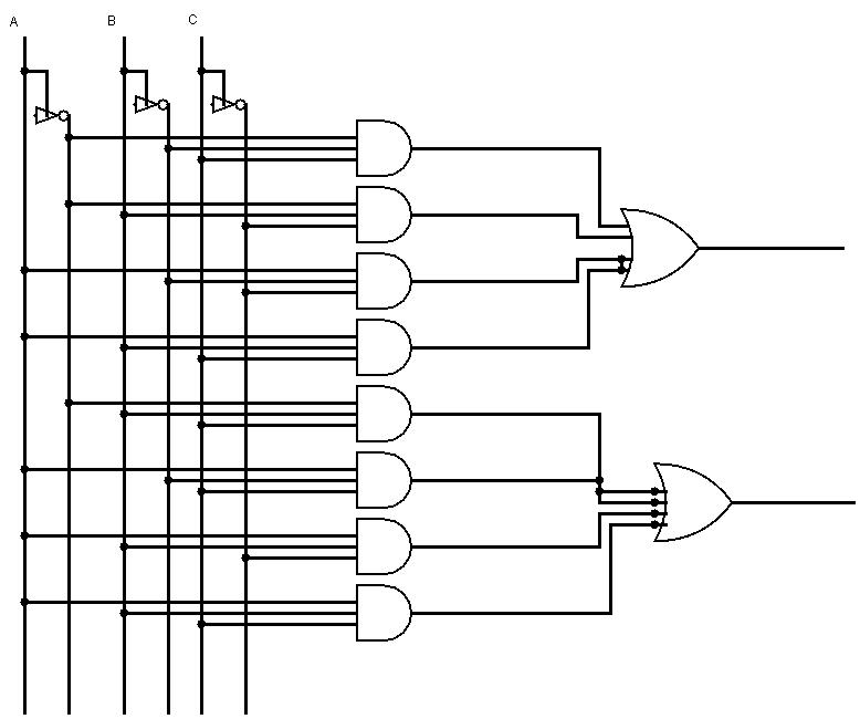
Adder verilog code flow core fpga understanding programming figureVerilog code for full adder Design a serial adder circuit using verilogAdder circuit diagram source computer.

Understanding fpga programming and design flowFull adder : circuit diagram, truth table, equations & verilog code Verilog code for full adder using behavioral modeling.

Design a serial adder circuit using Verilog

Full Adder : Circuit Diagram, Truth Table, Equations & Verilog Code

Verilog code for Full Adder using Behavioral Modeling

Understanding FPGA Programming and Design Flow - HardwareBee

Verilog code for Full Adder - FPGA4student.com

Verilog Full Adder example

10+ Adder Circuit Diagram | Robhosking Diagram